Power cuts have become a common occurrence around here, under the glamorous title of “load-shedding“. The local electrical utility has, for some years, and for many historical reasons, experienced periodic trouble meeting the demands placed upon the electricity network. It doesn’t happen all that often, but when it does, my area tends to go dark for about two hours, once or twice a day. This has led to a number of equipment failures; most of my equipment is behind some form of UPS, but most UPSes are designed to bridge less than five minutes of electrical outage, and not two hours.
So, I needed something a little more beefy for all my networking and storage equipment. Lockdown project!
After about two months of research (bigger off-the-shelf UPS? Extension packs?), I decided that I could build my own UPS that would last longer and be cheaper than the alternatives available to me. The Tesla Powerwall system has spawned a number of homegrown imitators, and the load-shifting design of the Powerwall met my needs precisely.
Moreover, by building a DC UPS, I could skip the conversion from DC and back to AC, which seems to account for a significant amount of power draw in most off-the-shelf UPSes; since all the essential equipment runs off either 12V (in the case of the network-attached storage/NAS and the network hub) or 24V DC (for the network router), or 5V DC for the Raspberry Pi, there was no need for AC power. The system was originally designed for 12V power, and so I chose a 4S configuration for the batteries, which ended up working well, even with the late addition of 24V output. The necessary components:
- A battery management system (BMS). This BMS handles the chosen 4S/12V configuration, has very large heat sinks, and is adjustable via Bluetooth. Having an adjustable configuration was important: I wanted to adjust the maximum and minimum battery voltages in order to prolong battery life as long as possible. (I also got the RS485 UART adapter, which now reads the BMS state for Prometheus/Grafana.)
- An AC/DC adapter, converting from 110/220VAC to 24VDC. The one I ended up getting was pretty chunky, accepting a fairly high wattage, and including a fan for when power is drawn. I chose 24V rather than 12V because the LiFePO4 cells operate at 12.7V to 14V, so 14V is needed to ensure that the cells will take power. It was also important to ensure that the adapter couldn’t backfeed into the grid!
- 2 x 9A/300W DC step-down converters, one to convert incoming 24V to a 14V constant charge profile for the battery, and one to regulate outgoing power at a stable 12V for 12V equipment (as the battery voltage could vary between 12.7V for discharged 4S LiFePO4 cells, and 14V for fully charged cells). These were massively overspecced (max current draw by the BMS is 1.2A @ 12V) to ensure good heat performance.
- 1 x 10A/150W DC step-up converter, to convert from the battery’s 12.7-14V to a stable 24V, for powering 24V equipment. Again, overspecced for those sweet sweet heatsinks.
- 1 x 3A/5V DC-USB step-down converter. This was to charge cellphones in case of a power cut, but now powers a Raspberry Pi that collects stats from the BMS (and other networking tasks).
- Copper wiring, solder, battery cell spacers, wood (for a box — I used meranti, which is sufficiently dense to increase its fire-resistance, at least in theory), connectors, terminal blocks, electrical tape, and other consumables.
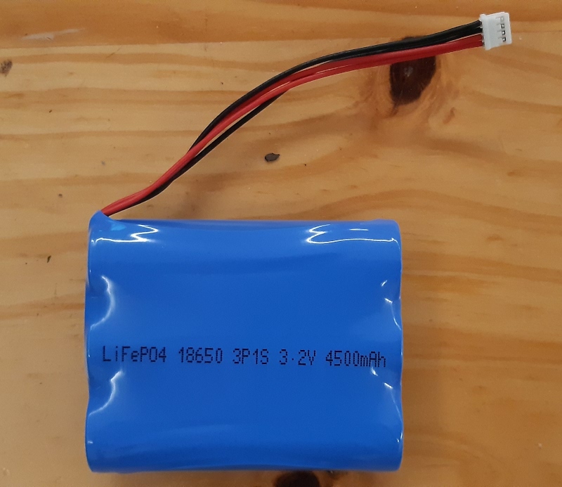
- And batteries! After much research, I decided to try and find Lithium Ferrite Phosphate (LiFEPO4) cells, which have a similar price point to Lithium Ion cells, but are much safer. They have excellent characteristics for this purpose, most important of which (after safety) is that 4 groups of cells (4S) closely matched my original requirement of a 12V system. I was incredibly lucky to find cells from the wonderful DIY Joe, who had bought a large batch for his own projects.
Based mostly on price, I bought 48 18650 1.5A cells, for a 12P4S (each group having 12 cells in parallel, providing 18A, with 4 groups in series) configuration, providing 72A at a nominal 3.3V, for about 230.4Wh. I had measured the power draw of all the devices I planned to run off the UPS, and come up with a maximum draw of 40W. So 230Wh would give me nearly 6 hours of runtime with all devices running at full power (I haven’t done a full load test yet, but in real-world conditions, I’d estimate runtime is closer to 20 hours). At its worst, load shedding could be 2 hours, 3 times a day, and there is no guarantee that the time between incidents would be sufficient to fully recharge the cells.
I did quite a bit of research into the dynamics of charging LiFePO4 cells; it appears that the best charge profile is to provide constant current (CC) at 18A (the technical term is C/1; C is the amperage of each group of parallel cells, in this case 18A) until the cell group reaches a charge of 3.6V, and then to provide constant voltage (CV) at 3.6V until the battery is pulling C/24 of current, or 0.75A (some sources say you can stuff your cells to the metaphorical gills, until they can’t take more than C/12, or 0.5A, of current; others offer the more conservative cut-off of C/20, or 0.9A).
However, I am not trying to saturate my cells: this is a (hopefully) long-lived and large-celled UPS, not a drone that needs as much power as you can cram into it! So I planned to cut off the charge at the relatively conservative 3.5V (I have since reduced this further to 3.45V), and entirely skip the CV step. In principle, increasing the minimum voltage and reducing the maximum voltage should result in vastly increased lifespan for the battery. So I would adjust the minimum voltage (the point at which the BMS refuses to provide any more power from the cells) on the BMS from 2.7V to 3.175V, and decrease the maximum voltage (the charge cutoff) from 3.65V to 3.45V.
The rest of the important values work backwards from this: if we want to charge 3.65V at 18A, we need a charger and BMS that can cope with 65.7W; I picked a 300W charger, and a BMS that maxes out at 120A (so about 6.6 times larger than neccessary: the shipping was sufficiently expensive that it made more sense to get the best BMS I could).
By early March, I had my cells; I had not yet ordered the BMS or chargers. Of course, at this point, lockdown intervened; I could only order the parts in June! Even if I had ordered in March, it wouldn’t have arrived any sooner than it did, in July.
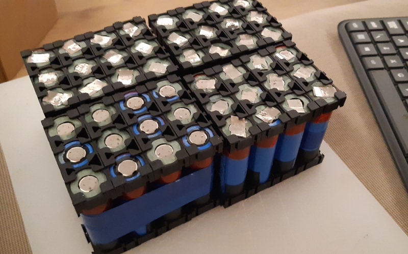
However, that did at least give me time to unbundle the 3P1S units that the batteries arrived in, and repackage them into 4 sets of 12, using battery spacers to keep each set together.
At this stage, I made the biggest mistake of the build: cutting away too much of the existing spot-welded tin strips that connected the three cells together. (Happily by the time I got to the second set of cells, I had learnt my lesson.) Batteries don’t react well to heat, so the best method of wiring up 18650s is to spot weld them with tin strips, which applies a huge amount of heat very quickly. Sadly, I don’t have a spot welder, so it was plain old solder (plus a bit of flux) for me. The remaining tin on the last three sets of batteries was enough to mediate the heat of the solder (and provide a stable base for the solder, so the wires were less likely to disconnect as I progressed and require re-soldering), but the first set, to this day, doesn’t charge quite as well as the other three.
Finally, by mid-June, I was able to place orders for the remaining equipment; most of the items arrived at the end of July. Unfortunately, by this point, I was so eager to get started that photos are few and far in between.
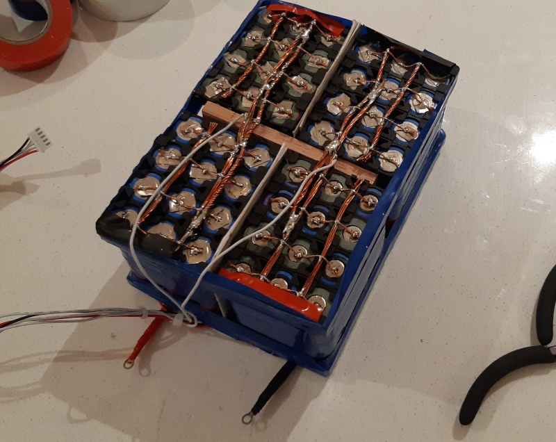
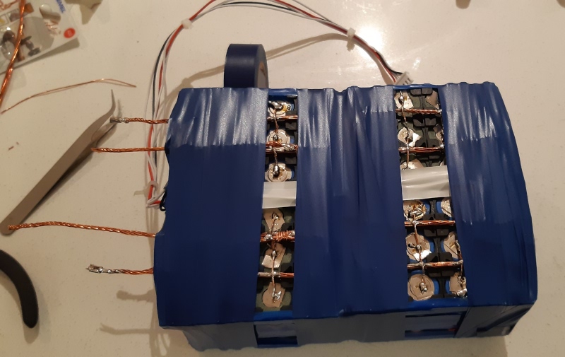
The next step was to wire together the groups of cells into a more permanent 4S configuration. I used fairly thick twisted copper wire as bus bars, with individual strands of copper to each wire, to act as a cheap fuse in case of over-current. (It works quite well; my testing was inadvertent but happily did not set fire to anything, damage any cells, or result in emergency room visits. It also confirmed my fire-proofing safety calculations: well worth the momentary clumsiness!)
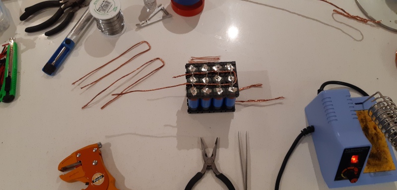
Having wired in the bus bars, I needed to connect the balance cables, which allow the BMs to detect and balance the voltage/charge of each group. Three of the wires go between each group (the white ones), the red and black go at the positive and negative terminal. Since a short-circuit of two 18A cells would be a powerful thing, I added a wooden spacer between the two sets of cells, to ensure that bus bars that should not touch stayed far apart.
Originally, I had arranged the bus bars to ensure that current went in one side (say, top left) and connected to the next cell on the opposite side (bottom right, in this example). This was to ensure that the current went through all the cells approximately evenly.
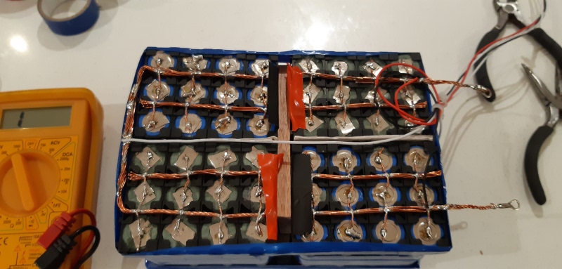
Later testing suggested that the copper bus bars that I was using weren’t enough to properly balance the batteries (although this may have simply been the use of a single negative wire to the BMS), so I ended up connecting the second row of bus bars, and adding a second set of positive and negative terminals.
In this photo, the terminals have lugs attached; lacking a proper crimping tool for these lugs, I eventually discarded the lugs and switched to using regular terminal blocks, which, when adding extra cabling, made the connections much safer and easier to manage.
Once I had finished wiring up the battery, I wrapped the whole thing in several layers of electrical tape (not having heat-strink tubing of quite that size!).
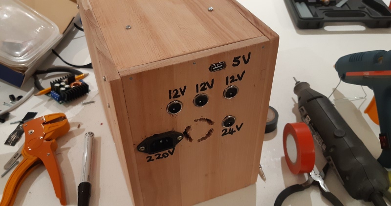
Having created my battery, I needed somewhere to put it for testing. So I built a box. (OK, my girlfriend built the box, since she’s much better at carpentry than I. All the untidy bits are mine though.) Sized to both fit all components in, and take up about the same space as the old UPS. We used wood and panel pins for this: the wood turned out to be just too thin to accommodate screws. However, it is reasonably strong, and doesn’t get moved much. On the front, I added holes for a fan; below, you can see the back, with 220V input, a 24V DC connector, 3 12V connectors, a 3A USB connector, and more holes for the rear fan.
Time to put everything together! The BMS has a slightly unintuitive connection structure: it doesn’t really interact with the positive wires; it draws some limited power (for operating power, Bluetooth and UART) from the positive balancing cable. So the positive wires link the charger output directly to both the battery and the various voltage regulator inputs. The negative wires provide the logical separation between mains and battery, with the BMS mediating battery charge and discharge. The charger provides about 14.1V, with enough current to both charge the battery and power the devices at the same time; the ~14.1V is slightly higher than the voltage that the battery can provide; this ensures the battery charges fully, and that when mains is available, the voltage regulators take power from the higher voltage source.
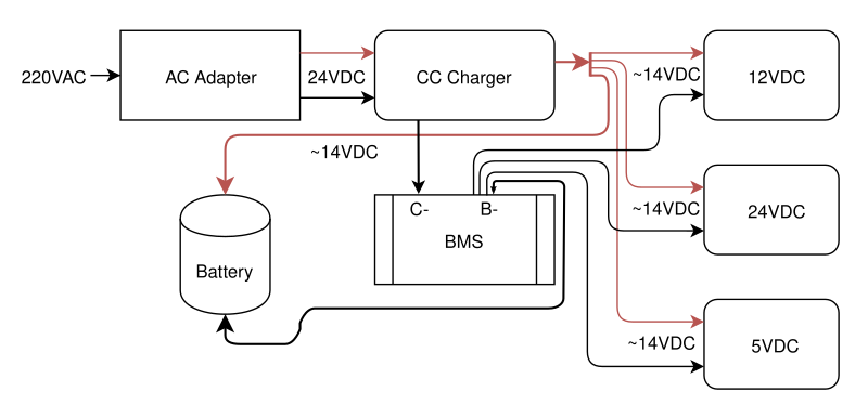
Following the diagram, the charger needed to have its knobs twiddled to set the output at 14.1V; its fellow step-down converter needed to output exactly 12V; and the step-up converter was set to output 24V. I was glad I had ordered extra modules, as one refused to respond to any adjustment to the knobs. (And because I burnt out one when an oversized cable popped out from its terminal and shorted everything. Big sparks! And a shift to one-size-down cable, and extra inspection of terminal screws…)
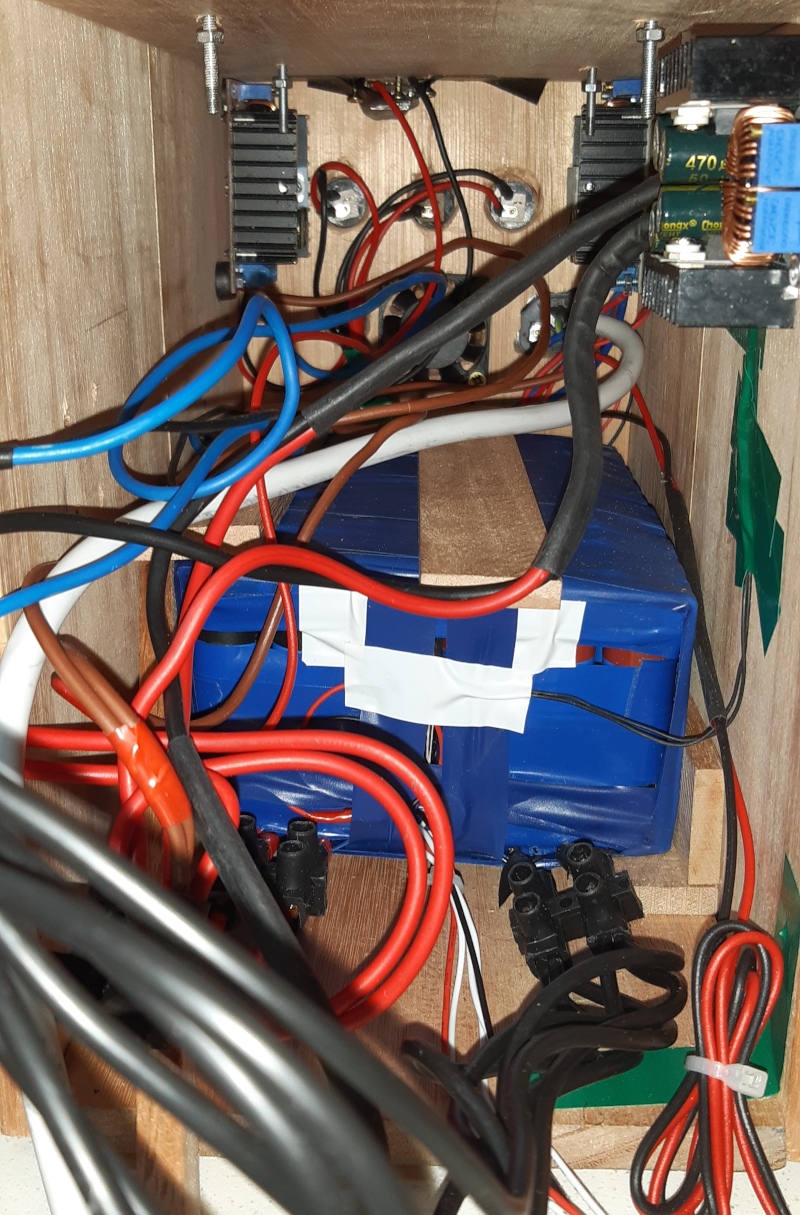
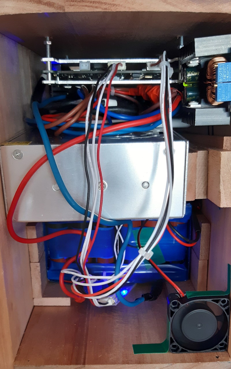
The next stage was to put everything together for testing; in the photo below, the AC adapter is the large silver box in the middle, with some leftover wood wedging it in place to make sure unconsidered gestures don’t create any shorts! The eventual aim was to bolt the adapter to the side panel of the box, but the adapter lacked screw holes on the sides. The blue light at the bottom is the BMS’s Bluetooth device; and the three-layered component is the BMS, with the metal sandwich acting as a heat sink.
The cabling creates something of a rat’s nest, which can’t have great thermal properties. The fan built into the adapter helps with this, but a future version will have a custom case (either laser-cut or 3D-printed), so that the longer wires, which allow me to pull out each device, are unnecessary and can be trimmed.
This is where I identified the aforementioned balancing issue: one cell group was charging up to 3.6V very quickly, causing the overcharge protection to kick in before the other cell groups were charged. After much research, I discovered the BMS website FAQ (not the main FAQ, but rather the one hidden in the download section recommended adding more cabling:
F.why does the first series cell has very low voltage and second series cell have high voltage ?
Please make sure to connect B- port with your own bold wire to the Battery negative port .the B- wire should be bold and short will be better , the thin and long wire connection to the B- port of the BMS will damage our BMS . please know it kindly in advance
The BMS was not able to push enough current to the battery through a single 12/14AWG cable; adding a second, and then third cable largely fixed the problem, but anything worth doing is worth overdoing: I ended up connecting six cables, and rewiring the battery to add a second row of bus bars. Two of the six battery-to-BMS cables connected to each BMS B- cable, and three of the six connected to the each of the two negative battery terminals.
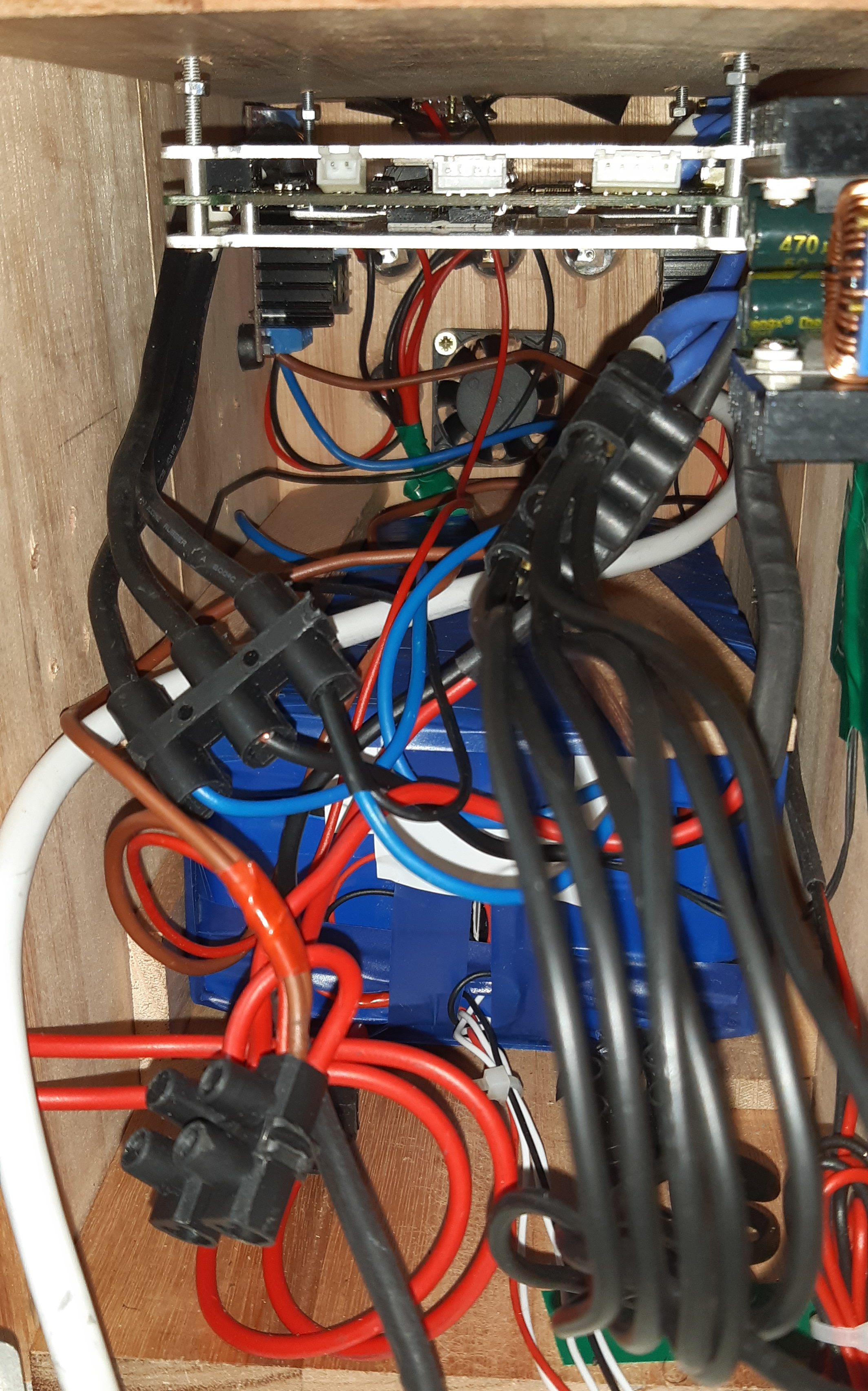
In part, the six-cable overkill was to try and address a last issue, where one cell group (again, the first group) stubbornly remained at a lower charge. Some online commentary suggested that this would come right over the course of a few months. It hasn’t yet; I strongly suspect the issue can be traced back to the cells themselves, and my soldering iron mistreatment of them. It’s not actually a big difference: the other three cells average 3.406V, while the first group averages 3.379V. This is a difference of 0.027V, within the recommended 0.03V BMS balancing difference. (Apparently reducing the balancing difference below 0.03V is not recommended, as it overworks the BMS and the cells.) The only reason I notice it is because the other three all have identical charges!
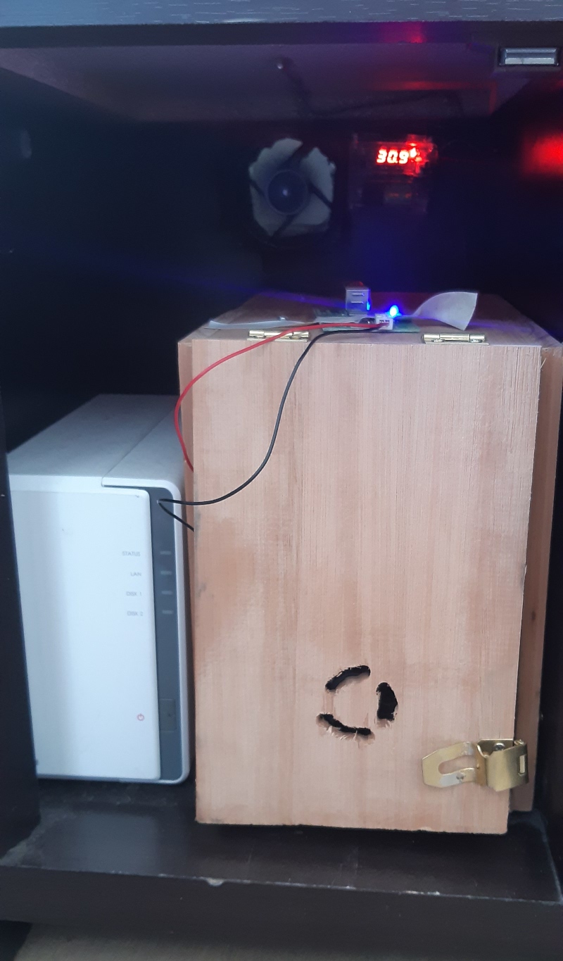
You’ll notice a circuit board taped to the top of the box in the photo above. This is a UART RS485-to-USB converter, which was added afterwards to feed information to the Raspberry Pi. In the next installment, I’ll show some screenshots from the Bluetooth app, as well sharing the the python script that I wrote to extract data from the BMS via this serial-to-USB cable. I’ll also show off its Prometheus export functions, my forthcoming experiments with InfluxDB, and some screenshots from the Prometheus data in Grafana.
Thanks for reading!